Circuit breaker reset
Circuit breaker reset
The various low voltage circuits (24 Vdc) are protected by an electronic distribution block. This monitors the load on each circuit and deactivates the power supply of a channel if the requested current is higher than the set threshold. The preset thresholds must not be changed. For information on the function of each channel and the settings, please refer to the diagram of the respective machine.
Before resetting a circuit breaker, it is important to clearly establish and eliminate the cause of the trip.
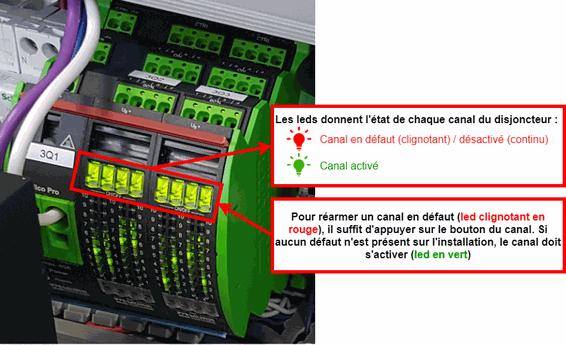
The electronic protection module is located in the electrical cabinet at the bottom rear of the Micro5. Located at the bottom right of the central board, each channel has an LED "bar graph" that indicates the trigger setting threshold. On top is an LED combined with a push button. This LED indicates the status of the channel:
Green: Channel activated, no fault.
Fixed Red :Channel disabled.
Flashing Red : Flashing red: Channel faulty.
To reset a faulty channel, press the channel button. If a fault is present on the channel (short circuit, overcurrent) it is not possible to activate the channel. It is imperative to eliminate the fault and remove the cause. If no fault is present on the channel, it can be reactivated.
There are no comments for now.