Maintenance
Completed
Axis frequency response measurement
Axis frequency response measurement
Bode diagram
This tool is used to check the machine's frequency response. This information is used to filter vibrations coming from resonances inherent to the mechanical design of the machine and helps in finding the optimal setting.
Prerequisites

The machine must be powered on.
The axes must be operational..
The PC must be equipped with the Triamec "Tam Explorer" software (7.12.0))
A standard pallet (h=12 mm) must be installed empty.
No tool must be in spindle (except when measuring the spindle))
Precautions
- During the whole procedure, the movements are controlled by the PC. Safety management by the PLC is deactivated.
- Keep other people away from the machine and remain nearby at all times.
- Maintain visual contact with the machine and its surroundings.
- Do not open the door during the procedure..
- Do not touch the machine during measurements, as this will distort the results.
- During the measurements, the machine is subjected to vibrations and emits sounds. Do not attempt to dampen the vibrations (by holding a partition, touching a component, etc.).
Procedure
Preparation
Set the axes manually to their neutral position (0 +/-3 mm)..
Open the electrical cabinet and connect the PC to the USB port on the Triamec drive.
Drive 100U1 --> X & B axes
Drive 110U1 --> Y & C axes
Drive 120U1 --> Z axis & Spindle
Between each measurement, check that the axes do not collide.
Only for the Z axis: Position a shim (20-40-60 mm) + a layer of foam and release the brake to take the measurements.
Only for the spindle: Insert an empty tool holder to perform the measurements..
Measures
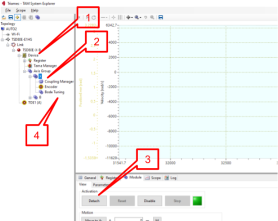
1. Right click on the device in the tree and select "Assign module".
2. Select the axis to be tested.
3. Attach the axis.
4. Select "Bode Tuning".
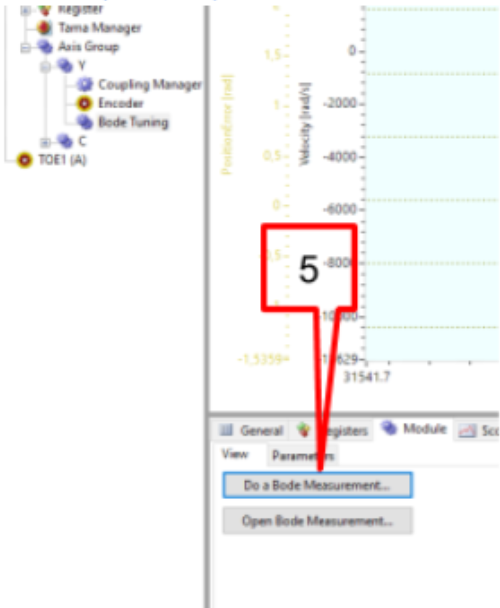
5. Click on "Do a Bode Measurement".
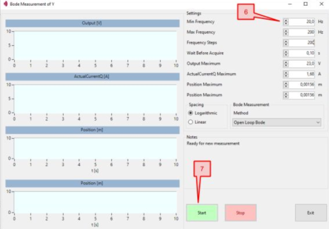
6. Enter the parameters: "Min Frequency", "Max Frequency" and "Frequency Steps"..
Measurement parameters
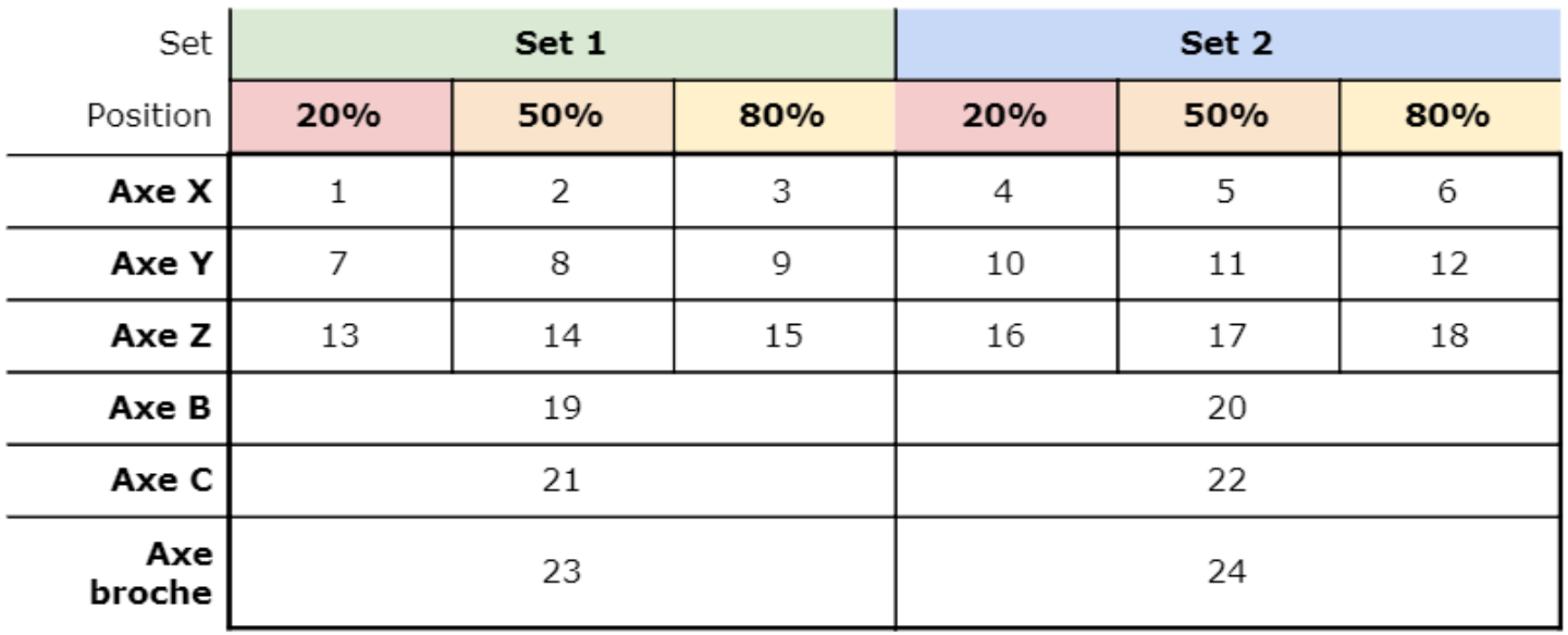
- For linear axes, perform measurements at 20, 50 and 80% of the stroke (+/- 10%).

- For rotary axes, carry out the measurements in the rest position (+/- 10%).
- For each position, perform 2 sets of measurements:

7. Start the test
8. At the end of the tests, record the results.
File name format: Bode AXIS-YYYY-MM-DD-Set?-POS.csv
example: Bode X-2020-03-09-Set2-50%.csv
9. At the end of the measurements for each axis, detach the axis.
10. Check that all communications are restored by activating manual homing on the CNC.
A complete measurement series comprises 24 files..
There are no comments for now.