Calibration
Machining calibration parts
The calibration part is the only test part which allows you to validate the operation of the Micro5. The design of this part and the machining program are conceived in such a way as to obtain reference faces on all planes in order to be able to determine the machine's geometric deviations. The measuring protocol gives clear indications and enables accurate diagnosis of the geometric state of the machine axes.
This part is produced during validation and acceptance of the machine on delivery and a measurement report is created. This report is supplied with the machine.
During the machine's life, this calibration part can be produced in order to check the operation and precision of the Micro5. If there is any doubt about the precision of the machine (e.g. after a crash), it is important to validate the calibration of the axis movements and zeros.
LThe customer can machine the calibration part directly. Auxiliary checking methods are required to measure the part (three-dimensional measurement, for example ( Zeiss DuraMax) . The results can be interpreted to validate the geometry and overall precision of the machine.
Prerequisites
The necessary equipment and tools are available in the shop.
The tools must be mounted in their cleats, measured, preset and placed in the tool holder disk.
The offsets must have been entered in the interface.
The blank must be mounted on the pallet and loaded directly into the machine by hand..
The machine must be in the initial position, without any error messages..
Machine offset settings
For a new 35 mm high brass cube mounted on a 12 mm high Yerly pallet:
G54 X=0 Y=0 Z= -37 B=0 C=0The Z0 of the program is on the finished side. Use 0.5 mm on Z for the roughing..
To re-machine a calibration cube that has already been machined, adjust the Z offset based on your part, activate the optional M1 stops and launch the first roughing operation with a 0.7 mm pass on Z.
Lower another 0.7 mm and run the full program.
Equipment
Consumable
Note:
- Each machining operation on the calibration block works to a Z depth of 1.4 mm
- The blank has a useful height of 15 mm (total height 30 mm)
Calibration kit
The kit calibration contains all the equipment necessary to perform the calibration.
Tools
T1: Finishing cutter Ø 1.8mm
/ output ↥ ~7.5mmT2: Finishing cutter Ø 1.8mm / sortie ↥ ~7.5mm
T3: Angle mill 90° Ø 0.6mm / output ↥ 7.5mm
T4: Hemispherical milling cutter Ø 2.0mm
/ output ↥ ~10mm
Note:
- The T1, T2 and T3 tools mounted should be close to 32.5 mm in length and 35 mm for T4.
Procedure
Load the machining program and execute.
The produced part should then be unloaded, cleaned and measured according to the protocol available below.
Program operations
Roughing, boring, contouring and milling B90 (T1))
Surfacing finish, bores (T2)
Finish Y+ C0, C90, C180 and C270
Finish X+ C0, C90, C180 and C270
Finish B90
Chamfers (T3)
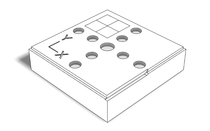
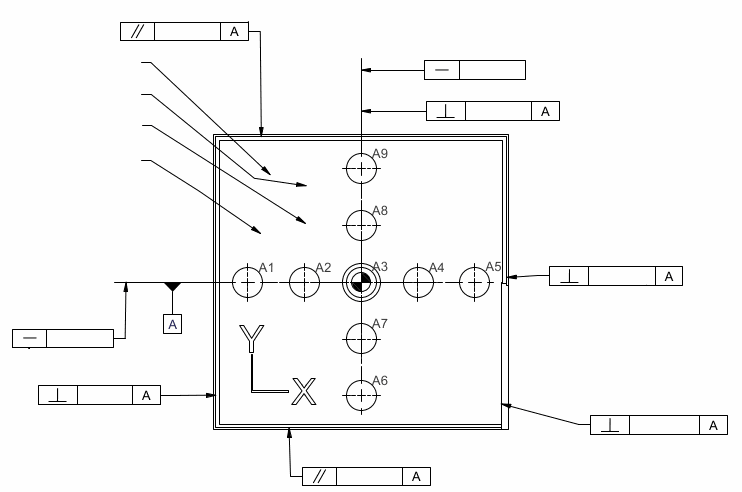
The Y+ and X+ finishes are made so as to obtain squares centered on the C rotation axis to determine the X and Y origins.
The calibration part machined according to the attached program can be determined:
the zeros of the X and Y axes according to the C rotation axis (reference)
cradle offset with B90 machining
the linearity of the XY movements with the bore centers
XY orthogonality
the linearity of the C axis with the angles of the sides of the squares
Measure procedure
The measurement of the control part can be carried out using an optical measuring bench or a three-dimensional measuring machine. The measurement report supplied with the Micro5 is made with a Zeiss Duramax CMM.
Coming soon: Program and control instructions
There are no comments for now.