Pallet management
Pallet management
A number of modifications must be made in the part machining program, compared to standard machining (1 part loaded manually):
The program should end with M17 instead of M30
Instead of writing the offset in the standard way (e.g. G54) we write a variable (e.g. G159=[V.P.OffsetFace1]) As a reminder, the machine offsets run from G54 to G59 and then G159 = 7 and so on. G54 corresponds to G159 = 1. The machine has a maximum of 97 offsets (G159 = 97)
We add an ACS with a variable on the C axis, which enables coordinate rotation (the C axis is not physically available when the machine is operating with the B axis at 90°).
Example of the main program shortcut
(…)
#VAR (Initialisation des variables)
V.P.OffsetFace1 = 0
V.P.OffsetFace2 = 0
V.P.ACSFace1C = 0
V.P.ACSFace2C = 0
#ENDVAR
P50 = 1 (Numéro de palette de départ)
P51 = 4 (Nombre de palettes à usiner)
$FOR P100 = P50,P50+P51-1,1 (Boucle : Premiere, Derniere, Increment)
$SWITCH P100
$CASE 1 (Palette 1)
G801[1] (Chargement Palette Position 1)
V.P.OffsetFace1 = 1 (G159 = 1)
V.P.OffsetFace2 = 2 (G159 = 2)
V.P.ACSFace1C = 0 (Correction Angle C Face1)
V.P.ACSFace2C = 0 (Correction Angle C Face2)
$BREAK
$CASE 2 (Palette 2)
G801[2] (Chargement Palette Position 2)
V.P.OffsetFace1 = 4 (G159 = 4)
V.P.OffsetFace2 = 5 (G159 = 5)
V.P.ACSFace1C = 0 (Correction Angle C Face1)
V.P.ACSFace2C = 0 (Correction Angle C Face2)
$BREAK
$CASE 3 (Palette 3)
G801[3] (Chargement Palette Position 3)
V.P.OffsetFace1 = 7 (G159 = 7)
V.P.OffsetFace2 = 8 (G159 = 8)
V.P.ACSFace1C = 0 (Correction Angle C Face1)
V.P.ACSFace2C = 0 (Correction Angle C Face2)
$BREAK
(...)
$DEFAULT
#MSG SYN HMI["Numero de palette hors plage"]
M30
$ENDSWITCH
L  C:\NC\Programme_exemple.nc (Programme d'usinage)
L  C:\NC\Soufflage.nc (Programme de soufflage palette)
$ENDFOR
G811 (Dechargement Palette)
(...)
M30
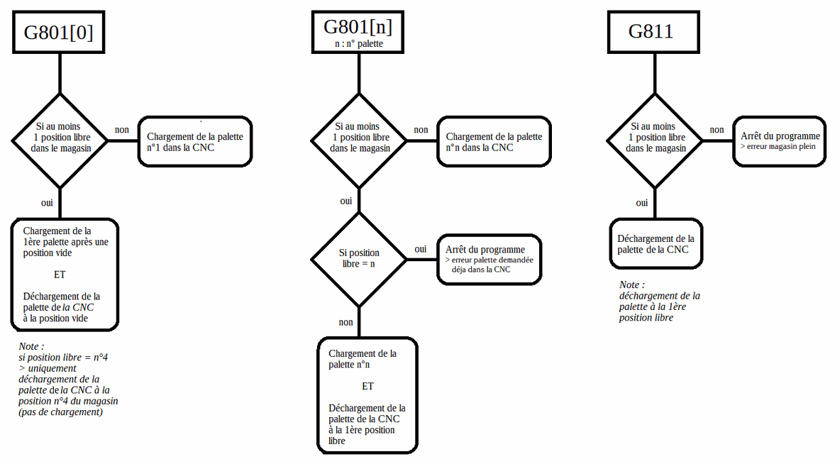
G codes for palletizing
G801 [pallet position]: This code brings the pallet from the magazine into the machining booth on the CNC side.
Example: G801[0]: This code brings the 1st unmachined pallet (1st pallet after an empty pallet in the magazine) from the magazine in the machining booth, CNC side. And unload the pallet in the CNC if there is an empty position in the magazine.
If the magazine is full, this code is used to bring pallet no. 1
If a pallet is already on the CNC side and another one is called, the SCARA will unload the pallet and bring the new one at the same time.
Example: G801[2] If there is no pallet on the CNC side, the SCARA will bring pallet number 2. If there is already a pallet on the CNC side, the SCARA will unload it and bring pallet number 2.
G811 will unload the pallet on the CNC side and store it in the magazine.
Program explanations
At the beginning of the program, the variables must be initialized. A value of 0 assigned to them. This is done in the block between #VAR and #ENDVAR. There is no need to modify anything in this part.
There are then 2 variables, P50 and P51, which allow you to choose the number of the starting pallet and the number of pallets you want to machine (this will disappear as it will soon be integrated into a page of the HMI for pallet selection). It is important to define the fixtures with a number since offsets are assigned to them.
Example of a loop
if you want to machine the 4 pallets in the magazine, set P50 = 1 (number of the starting pallet) and P51 = 4 (number of pallets to be machined).
If, for example, you only want to machine the first 2 pallets in the magazine, set P50 = 1 and P51 = 2.
If you want to machine only pallet number 3, set P50 = 3 and P51 = 1
CAUTION: Currently, we are obliged to physically fill the magazine with 4 pallets.
These 2 variables are included in the loop $FOR P100 = "A", "B", "C".
Loop logic:
A = first execution
B = last execution
C = loop increment
In our case, if for example we want to machine pallet number 1 and pallet number 3 of the magazine, we must modify the loop.
Example : P50 = 1
P51 = 3
$FOR P100 = P50,P50+P51-1,2
In this case, set the increment to 2 in order to jump from palette number 1 to palette number 3.
The #CASES are then completed with the information relating to the selected palette. First, enter code G801[] to bring the palette, then the offsets assigned to it and also, in the case of a top/bottom operation, a coordinate rotation offset for the top face and another offset for the bottom face.
Currently, we can only physically put 4 pallets in the magazine, however we can have several sets of fixtures that can be prepared while the machine is machining the workpiece.
The different variables for the offsets make it possible to adjust each fixture separately. We could machine all the fixtures with the same offset (for example G54) but it will not be possible to manage it if there are variations in the positioning of the workpiece on the fixture.
Let's consider the process for machining a watch main plate with a top/bottom fixture..
$CASE 1 (Pallets 1)
G801[1] (Loading Pallet Position 1)
V.P.OffsetFace1 = 1 (G159 = 1)
V.P.OffsetFace2 = 2 (G159 = 2)
V.P.ACSFace1C = 0 (Correction Angle C Face1)
V.P.ACSFace2C = 0 (Correction Angle C Face2)
$BREAK
In this case, we will machine the TOP face of the workpiece with offset G159 = 1 and the BOTTOM face of the workpiece with offset G159 = 2.
Offset G159 = 3 is assigned for backworking operations..
The offsets on the machine would be as follows (values are for information only)::
G159 = 1 : X-16 Y0 Z-60 B90 C90 (Face SUS)
G159 = 2 : X-16 Y0 Z-65 B90 C270 (Face SOUS)
G159 = 3 : X0 Y0 Z-72 B0 C0 (OP de reprise)
In the machining program, instead of setting G54 (G159 = 1), it uses the variables shown in the #CASES. The same applies for the angular offset managed via an #ACS
Face SUS
G159=[V.P.OffsetFace1]
#ACS ON[0,0,0,0,0,V.P.ACSFace1C]
Face SOUS
G159=[V.P.OffsetFace2]
#ACS ON[0,0,0,0,0,V.P.ACSFace2C]
For information, an #ACS allows you to perform a coordinate shift. In a top/bottom scenario, when the B axis is at 90°, the C axis is physically available to turn the part around the Z axis.
An ACS has 6 values, which correspond to the 3 linear and 3 rotary axes: #ACS (X,Y,Z,A,B,C) In our case, we will only use the C axis. The other axes can be corrected directly in the machine offsets.
Note that the value of "V.P.ACSFace1C" could come from a variable created during probing. For example:
V.P.ACSFace1C = V.P.ProbingFace1
This offset is useful if you want to be precisely aligned with the bores of the tray, for example.
These 2 values for the ACS are 0 as standard. The X, Y and angular offsets between the TOP and BOTTOM faces can be determined during inspection of the workpiece.
There is then a $DEFAULT line that allows you to manage a case that has not already been managed in the #CASE. For example, if you call up pallet number 5 when you have only created 4 cases, you can put a message on the HMI to indicate the error
For example: $ENDSWITCH indicates the end of the cases you have created.
By the time we get to this point, we have managed all the cases we want to machine. The machining program for the part must then be executed.
L C:\NC\Example_Program.nc (Machining program)
Enter L and then the file path. Several programs can be entered as a series. Let's consider a small blowing program to eliminate the chips near the base of the pallet in order to create a clean surface before the next pallet is brought.
CAUTION These programs must end with code M17 rather than code M30, otherwise the loop does not continue and stops at M30.
#ENDFOR indicates the end of the loop.
G811 is then added in order to unload the last pallet and place it back in the magazine at the end of the loop.
M30 then signals the end of the program. The M100 code can be added to make the machine's LEDs flash when the machine has finished machining all the pallets. The flashing can be stopped with a Reset.
If the machine is equipped with the probe magazine, there is no need to manage each pallet with a different (#CASE). A probing program is launched before machining, which writes the workpiece offsets in the machine offsets. (C.F. see e-learning on probing!)
For Inventor HSM users:
When post-processing the code, you must activate Palletization mode in the post-processor options. This allows the code to be extracted with the different variables used during palletization.

There are no comments for now.