Referencing on workpiece
Referencing on workpiece
Methods for part referencing
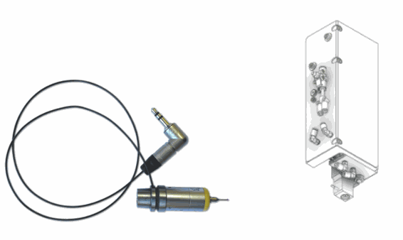
1) Part probe
The part probe is available in 2 versions. Either it is mounted manually in the spindle, or it is stored in a probe magazine, which will allow the SCARA robot to bring it to the spindle like a tool holder.
In terms of probing cycles, it is similar to other machines using this type of probe. For example, we can measure a diameter (inside or outside) at 3 or 4 points, a radius, a square-rectangle, orient an edge on Y or X, probe a height on Z, etc. The codes can be integrated directly into the CAM.
Link: Use of probe
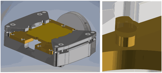
2) Positioning with pins (solid or split)
For example, to position a tray, we can adjust 2 pins that will position it. The degree of adjustment depends on the precision required. The bores of the tray can also be probed afterwards, for example for angular correction. These illustrations show top-and-bottom machining, however a standard Yerly pallet could equally be machined, for example when reworking a part.
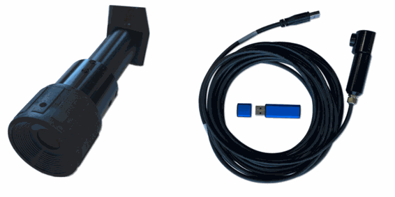
3) Centering with an optical lens
Centering can also be performed with spindle-mounted optical devices. There are 2 different versions: A device that allows the operator to view through a sight (like a monocular), or a version with a USB cable to display the image on the machine's screen. These systems are used in cases where the probe ball is too large to fit through a bore. Dial indexing would be a typical example.
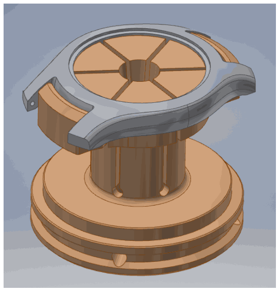
4) Machining the workpiece negative in an Ottet collet
Machining of an Ottet collet enables indexing based on the shape of the part. In most cases, centering is at X0 and Y0. This keeps the origin at the center during subsequent mounting of the part.
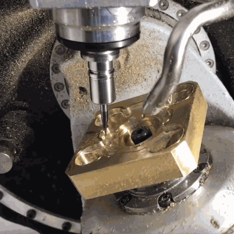
5) Original location with a milling cutter
As with any other machine, it is always possible to make contact with the surface of a workpiece with a milling cutter, descending in micron increments until a small mark is made on the workpiece. This marking may be problematic in some cases. To compensate for this, calibration shims can be placed between the tool and the workpiece.
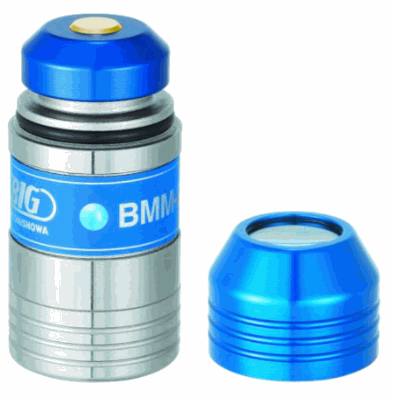
6) Height measurement with a "Base master" (height probe)
For the Z height measurement, the tip of the spindle against can be pressed against a small device which lights up a diode when contact is made.
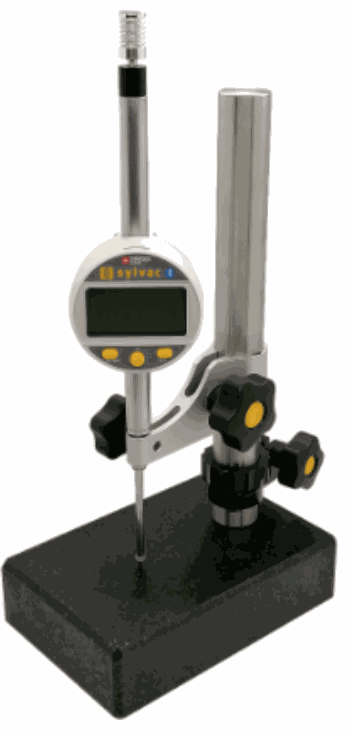
7) Height measurement with Sylvac comparator
We can measure the complete height of the fixture + workpiece using the Sylvac comparator (or other measuring device!) ). The pallet support face on the Yerly cartridge is set at Z-84.000 mm. It is therefore sufficient to add the height of the fixture + workpiece to determine the workpiece offset.
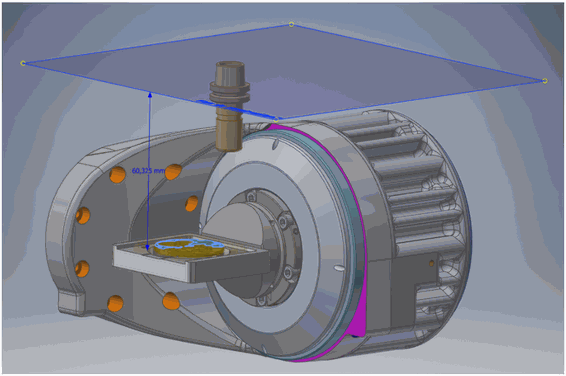
8) Theoretical measurement via CAD
For top-and-bottom machining, for example, we use the theoretical value of the pivot points (pallet support height -> B axis center = 18.6 mm) and (B axis center height -> Z0 machine = 65.4 mm). This gives us a starting point for the adjustment. To obtain the precise value, the actual value of the machine pivot points must be used. These values vary by a few hundredths, due to a stack of workpieces and therefore tolerances.
Rating
There are no comments for now.