[016 549] Probe
Probe
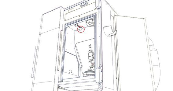
The automatic probe (option) allows a wired probe to be stored inside the machining booth and loaded in the machining spindle using the SCARA, in order to perform probing measurements. The unit is fixed at the top left in the machining booth and connected to the Micro5 by a connector.
The probe can also be used without automatic loading. It must then be manually installed in the spindle by the operator. The operation remains the same.
Connection
The probe is connected to the female connector on the top wall of the machining booth. When the probe is not in use, plug the female connector with the male connector attached to the cabin.

Important note
When the probe is not in use, plug the female connector with the male connector attached to the cabin.
The probe must not be used for automatic loading when oil is used!
The probe magazine must not be left without a tool for a prolonged period (>10 min)
The probe is not suitable for use with oil.
Use of the probe
To use the probe, you must load the probing cycle file. This file must be transferred to the Micro5, in the C:\nc\process\ folder
The rest of the article uses the example files to illustrate and explain the use of probing.
Examples of use
Example file to download and place in the C:\nc\ folder
The probing sequences are designed to be run on a 40x40 mm machined calibration part with the G54 offset set to have the Z0 on the top face.
Download
Important
The probe must be calibrated when first used (two calibrations: X/Y and Z)
Le palpeur doit toujours être monté à la même orientation pour que la calibration soit correcte
In manual mode: Facing the operator
Without store: Facing the operator
With the store: opposite
The touch probe must always have the tool number 999
The probe being a fragile element, reduce the feeds during your first probings <10%.
Starting conditions
The approach and offset to be used must be added manually before starting a probing cycle
Set the probe length (approximate) Leave the tool radius at 0.
Configure the offset and activate it before starting the probing cycle
Several probing cycles are provided in the supplied macro. They are configured with the parameters included in the macro execution.
Cycles available
XY probe calibration (requires a bore centered on X0 Y0) and length
Bore/Square and rectangle pocket
-->Indicates the center (XY offset setting optional)
Round/square/rectangular boss
-->Indicates the center (XY offset setting optional)
Z height measurement
-->Indicates height (Z offset setting optional)
XYZ corner
--> Corner coordinates (XYZ offset setting optional)
C orientation
--> Indicates C orientation error (C offset optional)
Modal operation
All cycles (except XY probe calibration and length calibration) can be started in MODAL mode.
This allows the cycle to be re-run after each XY movement.
Useful to execute several identical cycles in different XY positions
You have to add:
MODAL_MOVE in the cycle parameter list
#DISABLE MODAL CYCLE after the last probing occurrence
The machine must be positioned on XY before the cycle is started and parameters @P1 and @P2 must not be defined.
If another cycle configuration parameter needs to be changed for a new cycle iteration, the MODAL mode cannot be used.
ATTENTION
The probed values must be retrieved in separate variables at each measurement if they are to be used later for calculations.
--> See the example "MeasureZ" for the calculation of the average of 4 measures Z
Manual approach
For boring/boss, height measurement and cornering cycles, it is possible to bring the probe along XY manually and then start the cycle without the @P1 and @P2 parameters. The XY position at the start of the cycle will be taken as the reference position.
ATTENTION
The Z offset and the tool must be correctly configured.It may be necessary to increase the parameters for approach travel (@P9) and measurement overtravel (@P10).

Remarks
The probe is automatically called by the probe cycle when the probe magazine is present.
If the magazine is not present, the cycle asks to mount it manually. --> If it is already mounted, this step is directly acknowledged
With the optional parameter @P49=1 it is possible to force manual operation
The texts below are selectable ("Ctrl+C" / "Ctrl+V")
Probe length calibration
; Calibration longueur palpeur sur la face de référence Yerly
L CYCLE [NAME=Probing.cyc \
@P1=10    \; Position X absolue (option)
@P2=-10   \; Position Y absolue (option)
@P3=0     \; Position Z absolue surface
@P4=1     \; Degagement Z relatif
@P9=0.25  \; Course premesure
@P10=2    \; Surcourse premesure/mesure
@P11=10   \; Vitesse avance mesure
@P49=0    \; 0 Montage palpeur auto si magasin, 1 montage manuel seulement (optionnel, defaut = 0)
@P50=101  \; Type de mesure Calibration longueur palpeur
]
Probe calibration XY
; Calibration decentrage bille
L CYCLE [NAME=Probing.cyc \ ; Calibration palpeur XY
@P1=0     \; Position X absolue (option)
@P2=0     \; Position Y absolue (option)
@P3=0     \; Position Z absolue surface
@P4=1     \; Degagement Z relatif
@P5=-0.5  \; Hauteur mesure Z relatif a la surface
@P6=4     \; Diametre
@P8=1     \; Diametre bille palpeur
@P9=0.25  \; Course premesure
@P10=2    \; Surcourse premesure/mesure
@P11=10   \; Vitesse avance mesure
@P49=0    \; 0 Montage palpeur auto si magasin,
          \; 1 montage manuel seulement (optionnel, defaut = 0)
@P50=100  \; Type de mesure 100 = calibration palpeur
]

; Affiche resultat sur le HMI
#MSG SYN HMI["Calibration: X: %fmm, Y: %fmm", V.P.OffX, V.P.OffY]
; Ecrit le resultat dans fichier texte
#MSG SAVE EXCLUSIVE["Calibration: X: %fmm, Y: %fmm", V.P.OffX, V.P.OffY]
Bore / square or rectangle pocket
G0 X0 Y0 ; Prepositionner pour MODAL_MOVE uniquement
L CYCLE [NAME=Probing.cyc \
@P1=0      \; Position X centre (supprimer pour MODAL_MOVE)
@P2=0      \; Position Y centre (supprimer pour MODAL_MOVE)
@P3=0      \; Position Z absolue surface
@P4=1      \; Degagement Z relatif
@P5=-0.5   \; Hauteur mesure Z relatif a la surface
@P6=4      \; Dim X alesage
@P7=4      \; Dim Y alesage (seulement si different de @P6)
@P8=1      \; Diametre bille palpeur
@P9=0.25   \; Course premesure
@P10=1     \; Surcourse premesure/mesure
@P11=10    \; Vitesse avance mesure
@P40=0     \; Offset à renseigner G54=1, G55=2, ...
@P45=0     \; Pas de sauvegarde interne au cycle
@P49=0     \; 0 Montage palpeur auto si magasin,
           \; 1 montage manuel seulement (optionnel, defaut = 0)
@P50=0     \; Type de mesure alesage
;MODAL_MOVE \; Seulement pour mode modal
]
V.P.X3 = V.P.PosMesX                                                ; Position X
V.P.Y3 = V.P.PosMesY                                                ; Position Y
V.P.Circ3 = V.P.Circ                                                ; Circularite
#MSG SYN HMI["Centre 3: X: %fmm, Y: %fmm", V.P.X3, V.P.Y3]          ; Affiche sur le HMI
#MSG SAVE EXCLUSIVE["Centre 3: X: %fmm, Y: %fmm", V.P.X3, V.P.Y3]   ; Ecrit dans fichier texte
G0 X-15 Y0                                                          ; Positionne pour 2e cycle
V.P.X1 = V.P.PosMesX - V.P.X3                                       ; Calcul delta X
V.P.Y1 = V.P.PosMesY - V.P.Y3                                       ; Calcul delta Y
V.P.Circ1 = V.P.Circ                                                ; Circularite
#MSG SYN HMI["Centre 2: X: %fmm, Y: %fmm", V.P.X1, V.P.Y1]          ; Affiche sur le HMI
#MSG SAVE EXCLUSIVE["Centre 1: X: %fmm, Y: %fmm", V.P.X1, V.P.Y1]   ; Ecrit dans fichier texte
#DISABLE MODAL CYCLE
Round / square / rectangle embossing
L CYCLE [NAME=Probing.cyc \ ; Centre cube @P1=0 \; Position X absolue (option) @P2=0 \; Position Y absolue (option) @P3=0 \; Position Z absolue surface @P4=1 \; Dégagement Z relatif @P5=-2 \; Hauteur mesure Z relatif à la surface @P3 @P6=40 \; Dimension X @P7=40 \; Dimension Y (seulement si different de @P6) @P8=1 \; Diametre bille palpeur @P9=1 \; Course prémesure @P10=2 \; Surcourse prémesure/mesure @P11=10 \; Vitesse avance mesure @P40=0 \; Offset à renseigner G54=1, G55=2, ...
@P45=0 \; Pas de sauvegarde interne au cycle
@P49=0 \; 0 Montage palpeur auto si magasin, \; 1 montage manuel seulement (optionnel, defaut = 0)
@P50=1 \; Type de mesure bossage;MODAL_MOVE \; Seulement pour mode modal] V.P.CentreX = V.P.PosMesX ; Position X V.P.CentreY = V.P.PosMesY ; Position Y ;V.P.Circ3 = V.P.Circ ; Circularite ; Affiche resultat sur le HMI #MSG SYN HMI["Centre Cube: X: %fmm, Y: %fmm", V.P.CentreX, V.P.CentreY] ; Ecrit le resultat dans fichier texte #MSG SAVE EXCLUSIVE["Centre Cube: X: %fmm, Y: %fmm", V.P.CentreX, V.P.CentreY]
Measure Z
G0 X35/2 Y35/2 ; Prepositionner pour MODAL_MOVE uniquement
L CYCLE [NAME=Probing.cyc \ ; Mesure Z1
@P1=0      \; Position X (supprimer pour MODAL_MOVE)
@P2=0      \; Position Y (supprimer pour MODAL_MOVE)
@P3=0      \; Position Z absolue surface
@P4=1      \; Dégagement Z relatif
@P9=1      \; Course prémesure
@P10=2     \; Surcourse prémesure/mesure
@P11=10    \; Vitesse avance mesure
@P12=90    \; Orientation mesure C 0 +X, 90 +Y, 180 -x, 270-Y
@P40=0     \; Offset à renseigner G54=1, G55=2, ...
@P45=0     \; Pas de sauvegarde resultat interne au cycle
@P49=0     \; 0 Montage palpeur auto si magasin,
           \; 1 montage manuel seulement (optionnel, defaut = 0)
@P50=10    \; Type de mesure Z
;MODAL_MOVE \; Seulement pour mode modal
]

V.P.MesZ1 = V.P.PosMesZ

G0 X-35/2 Y35/2          ; Mesure Z2
V.P.MesZ2 = V.P.PosMesZ

G0 X-35/2 Y-35/2         ; Mesure Z3
V.P.MesZ3 = V.P.PosMesZ

G0 X35/2 Y-35/2          ; Mesure Z4
V.P.MesZ4 = V.P.PosMesZ

; Affiche resultat sur le HMI
#MSG SYN HMI["Z Moyen: %fmm", [V.P.MesZ1 + V.P.MesZ2 + V.P.MesZ3 + V.P.MesZ4]/4]
; Ecrit le resultat dans fichier texte
#MSG SAVE EXCLUSIVE["Z Moyen: %fmm", [V.P.MesZ1 + V.P.MesZ2 + V.P.MesZ3 + V.P.MesZ4]/4]
Probe check
In order to guarantee the highest level of accuracy, each element must be perfectly mounted and operated. The probe is a sensitive element, its correct assembly guarantees its correct operation and an accurate result.
The probe is mounted on a bar adapted to the standard used on the Micro5. It can therefore be mounted in the spindle cone as well as in the probe magazine (option).
The following procedure allows you to check that the probe is correctly mounted on its cleat:
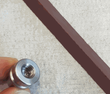
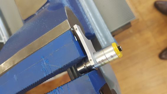
1) Pass the oil stone over the top face, so that the face is clean and flat (no burrs or dents)
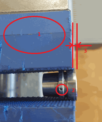
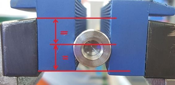
2) In the vice equipped with the rubber jaws (1), centered in height (4), clamp the cleat with moderate force so that :
have the wire up (2)
have the support face protruding (3)
2) In the vice equipped with the rubber jaws (1), centered in height (4), clamp the cleat with moderate force so that :
have the wire up (2)
have the support face protruding (3)
have the support face protruding (3)
3) Using the wrench provided, tighten the probe on its support.
Caution: the probe will turn in the jaws, do not damage the wire
Warning: the key has two sides. Only one has the right size
3) Using the wrench provided, tighten the probe on its support.
Caution: the probe will turn in the jaws, do not damage the wire
Warning: the key has two sides. Only one has the right size
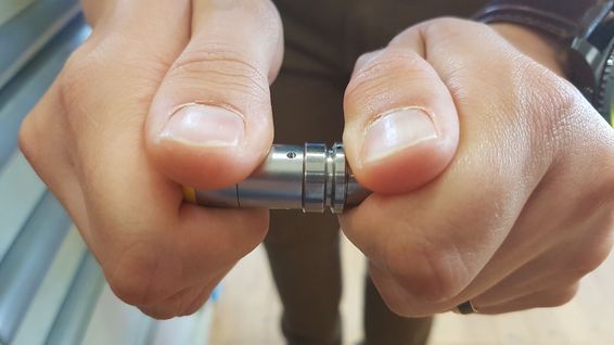
4) Control: It must be impossible to loosen the probe by hand.
There are no comments for now.